
O.R.C Family Datasheet
Organic Rankine Cycle · R245fa Working Fluid · Radial-Inflow Turbine
POWER+ Generator — Model: S-ORC 75
Single-engine waste heat recovery and small distributed biomass
Product Overview
Scope’s S-ORC 75 is the family’s distributed waste-heat module, sized for a single low-grade heat source in the 0.6 MWth thermal-input class. The S-ORC 75 employs a two-stage Radial-Inflow Turbine (RIT) expander coupled to a grid-tie generator, with R245fa as the working fluid. The radial-inflow turbine architecture allows for high cycle efficiency across a wide range of inlet thermal conditions. This unit is engineered for retrofit onto a single reciprocating engine, a small biomass boiler, or a single wellhead-class heat source — making it the entry-point for distributed onsite power generation, fleet pilots, and CHP integration where the heat source is one identifiable piece of equipment.
| Temperature Range: 150-280°F (65-138°C) | Max Power Output: 75 kW @ 60Hz | Temperature Delta from Hot Inlet: 144°F (80°C) |
| Flow Rate: 15-38 GPM (0.9-2.4 L/s) | Utility Connection: 3-Phase 380-500V / 50, 60 Hz | Flow Rate: 24-53 GPM (1.5-3.3 L/s) |
| Thermal Input: 1.4 – 2.4 MMBTU/hr (407-698 kW) | Working Fluid: R245fa, 200 lbs (90 kg) | Thermal Output: 1.2 – 2.1 MMBTU/hr (353-605 kW) |
| Higher Temps or non water/glycol fluids possible with interface heat exchanger | Weight: 5,800 lbs Dimensions: 6.0′ x 8.0′ x 7.0′ (W*L*H) (1.8m x 2.4m x 2.1m) | Ambient Temperature Range: 32-104°F (0 – 40°C) |
*Thermal input requirements increase with elevated ambient temperatures / heat sink conditions. **Temperature delta between inlet hot and cold water.
Best Heat Sources
- Reciprocating engine jacket water (90-105°C, single-engine)
- Reciprocating engine exhaust gas (300-450°C via interface HX)
- Small biomass boiler hot water loop (95-130°C)
- Pyrolysis / biochar process flue gas
- Single thermal oxidizer (low duty)
- Geothermal / co-produced water (single low-flow well)
Best Applications
- Single gas-engine waste heat recovery (jacket water + exhaust integration, 1-2 MW shaft class engines such as Waukesha L7044, Caterpillar G3516)
- Single wellhead reciprocating engine retrofit (oilfield gas-fired prime movers)
- Small biomass boilers (animal bedding, woody biomass at 1.5-2.5 MWth firing rate)
- Single-unit pyrolysis / biochar facility flue gas
- Distributed dairy / food processing CHP
- Pilot deployment for fleet validation
Cycle & Output
Recuperated ORC with two-stage Radial-Inflow Turbine
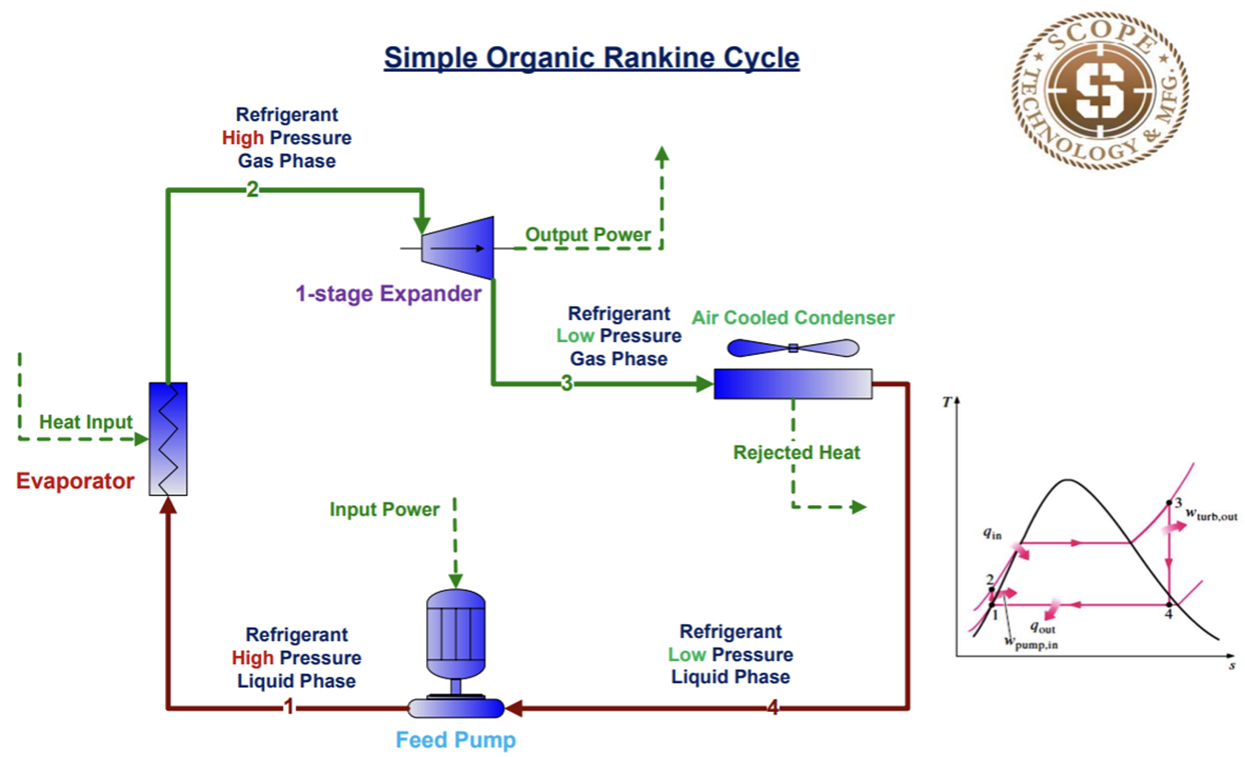
Heat Source → Evaporator → RIT Expander → Recuperator → Condenser → Feed Pump → Recuperator → back to Evaporator
- Working Fluid: R245fa (subcritical)
- Tmax: 275°F (135°C)
- Pmax: 174 psi (12 bar)
- Cycle ηth: 12.9%
- Expander ηis: ~78% design point
Clean Energy Output
Up to 75 kW emissions-free electrical power
+ Heat sources that are not water or glycol mixture will require an interface heat exchanger and hot water loop. Higher-temperature thermal-oil and direct-steam interface configurations available on request.
Design Attributes & Engineering Detail
Design Attributes
- Built to ASME and CE Standards
- Two-stage Radial-Inflow Turbine Expander
- Grid-tied Induction Generator (PMG option)
- Proprietary PLC and HMI Controls
- Sound Pressure (@1 Meter): 85-89 dBA (size-dependent)
- Power Factor: output-dependent >0.9 lagging
- Outdoor Rated, IP54 enclosure
- Design Life: 25 years
- Low-GWP Working Fluid (R245fa, GWP 1030)
- Recuperated cycle for improved ηth
- Black-start optional on certain configurations
Product Highlights
- Zero direct emissions during operation
- Zero-carbon power when paired with renewable heat
- Skid-mount, plug-and-play installation
- Remote monitoring via VPN
- Low routine maintenance
- Minimal footprint vs. equivalent steam Rankine
- Qualifies for IRA and state-level incentives
- Grid protection relay input
- IEEE 1547-2018 compliant grid-tie
Design-Point Engineering Data
| Parameter | Value | Notes |
|---|---|---|
| Net Electrical Output | 75 kW | At design conditions, 60 Hz |
| Gross Electrical Output | 79 kW (approx.) | 5% parasitic load assumed |
| Cycle Net Thermal Efficiency | 12.89% | R245fa subcritical, recuperated |
| Heat Input (Q_in) | 0.58 MWth (1.99 MMBtu/hr) | Evaporator + economizer |
| Heat Rejected (Q_out) | 0.50 MWth (1.72 MMBtu/hr) | Condenser to heat sink |
| Working Fluid Mass Flow | 2.53 kg/s (20.1 lb/s) | R245fa |
| HTF Mass Flow (water) | 1.40 kg/s (25 GPM) | 180→100°C ΔT |
| Turbine Inlet Temperature | 275°F (135°C) | Below R245fa critical (Tc=154°C) |
| Turbine Inlet Pressure | 174 psi (12 bar) | Subcritical operation |
| Condensing Temperature | 95°F (35°C) | 10K terminal ΔT from ambient |
| Condensing Pressure | ~30 psi (2.1 bar) | R245fa at 35°C saturation |
| Expander Isentropic Efficiency | ~78% | RIT design point, size-scaled |
Expander Architecture Note
The Scope S-ORC 75 uses a two-stage radial-inflow turbine (RIT) expander integrated with a grid-tie induction generator on a common skid. R245fa working fluid is chosen for its match to low-to-medium temperature heat sources (90-150°C heat source class) and its established compatibility with HVAC-derived components for ORC service. The cycle operates subcritical, respecting the R245fa critical temperature of 154°C with a typical 19K margin at design point. The RIT architecture is selected for cycle efficiency optimization at this temperature class; reverse-compressor and screw-expander alternatives are available on request for cost-optimized configurations at the smaller sizes (75-500 kWe class).
For engineering support, site integration studies, or ordering:
Scope Technology & Manufacturing | 14531 FM 529 E, Suite 160, Houston, TX 77095 | www.scopemfg.com
POWER+ Generator — Model: S-ORC 250
Gas gathering compressor stations and mid-scale industrial process WHR
Product Overview
Scope’s S-ORC 250 targets the mid-scale waste-heat opportunity in the 2 MWth thermal-input class — the size range where a midstream gas gathering compressor station, a paired engine installation, or a mid-sized industrial process makes onsite power generation strongly economic. The S-ORC 250 employs a two-stage Radial-Inflow Turbine (RIT) expander coupled to a grid-tie generator, with R245fa as the working fluid for low-to-medium temperature heat sources. The unit is engineered for stable load-following operation as heat source duty varies through the day, and it pairs naturally with NOV-style centrifuge separation loads in midstream produced-water treatment applications where Scope’s recovered power directly offsets the electrical demand of the water-handling equipment.
| Temperature Range: 150-280°F (65-138°C) | Max Power Output: 250 kW @ 60Hz | Temperature Delta from Hot Inlet: 144°F (80°C) |
| Flow Rate: 47-118 GPM (3.0-7.4 L/s) | Utility Connection: 3-Phase 380-500V / 50, 60 Hz | Flow Rate: 77-165 GPM (4.8-10.4 L/s) |
| Thermal Input: 4.4 – 7.6 MMBTU/hr (1298-2225 kW) | Working Fluid: R245fa, 550 lbs (250 kg) | Thermal Output: 3.8 – 6.5 MMBTU/hr (1117-1915 kW) |
| Higher Temps or non water/glycol fluids possible with interface heat exchanger | Weight: 12,500 lbs Dimensions: 8.0′ x 12.0′ x 8.0′ (W*L*H) (2.4m x 3.7m x 2.4m) | Ambient Temperature Range: 32-104°F (0 – 40°C) |
*Thermal input requirements increase with elevated ambient temperatures / heat sink conditions. **Temperature delta between inlet hot and cold water.
Best Heat Sources
- Aggregated reciprocating engine jacket water (multi-engine pad)
- Reciprocating engine exhaust gas (multi-engine, via shared HX)
- Mid-scale biomass boilers and steam systems
- Gas compressor cooling water and discharge cooling
- Industrial process hot-water and low-pressure steam returns
- Geothermal brine / co-produced water from multi-well pads
Best Applications
- Gas gathering compressor station heat recovery (3-5 MW gas engine pad)
- Two- or three-engine reciprocating compressor pads (Permian, Eagle Ford, Bakken)
- Midstream produced-water treatment stations powering centrifuge separation
- Mid-scale biomass boilers (3-6 MWth firing rate)
- Industrial process heat — paper mill, dairy, food processing
- Geothermal co-produced water from multi-well pads
Cycle & Output
Recuperated ORC with two-stage Radial-Inflow Turbine
Heat Source → Evaporator → RIT Expander → Recuperator → Condenser → Feed Pump → Recuperator → back to Evaporator
- Working Fluid: R245fa (subcritical)
- Tmax: 275°F (135°C)
- Pmax: 174 psi (12 bar)
- Cycle ηth: 13.5%
- Expander ηis: ~82% design point
Clean Energy Output
Up to 250 kW emissions-free electrical power
+ Heat sources that are not water or glycol mixture will require an interface heat exchanger and hot water loop. Higher-temperature thermal-oil and direct-steam interface configurations available on request.
Design Attributes & Engineering Detail
Design Attributes
- Built to ASME and CE Standards
- Two-stage Radial-Inflow Turbine Expander
- Grid-tied Induction Generator (PMG option)
- Proprietary PLC and HMI Controls
- Sound Pressure (@1 Meter): 85-89 dBA (size-dependent)
- Power Factor: output-dependent >0.9 lagging
- Outdoor Rated, IP54 enclosure
- Design Life: 25 years
- Low-GWP Working Fluid (R245fa, GWP 1030)
- Recuperated cycle for improved ηth
- Black-start optional on certain configurations
Product Highlights
- Zero direct emissions during operation
- Zero-carbon power when paired with renewable heat
- Skid-mount, plug-and-play installation
- Remote monitoring via VPN
- Low routine maintenance
- Minimal footprint vs. equivalent steam Rankine
- Qualifies for IRA and state-level incentives
- Grid protection relay input
- IEEE 1547-2018 compliant grid-tie
Design-Point Engineering Data
| Parameter | Value | Notes |
|---|---|---|
| Net Electrical Output | 250 kW | At design conditions, 60 Hz |
| Gross Electrical Output | 262 kW (approx.) | 5% parasitic load assumed |
| Cycle Net Thermal Efficiency | 13.48% | R245fa subcritical, recuperated |
| Heat Input (Q_in) | 1.85 MWth (6.33 MMBtu/hr) | Evaporator + economizer |
| Heat Rejected (Q_out) | 1.60 MWth (5.44 MMBtu/hr) | Condenser to heat sink |
| Working Fluid Mass Flow | 8.00 kg/s (63.5 lb/s) | R245fa |
| HTF Mass Flow (water) | 4.40 kg/s (79 GPM) | 180→100°C ΔT |
| Turbine Inlet Temperature | 275°F (135°C) | Below R245fa critical (Tc=154°C) |
| Turbine Inlet Pressure | 174 psi (12 bar) | Subcritical operation |
| Condensing Temperature | 95°F (35°C) | 10K terminal ΔT from ambient |
| Condensing Pressure | ~30 psi (2.1 bar) | R245fa at 35°C saturation |
| Expander Isentropic Efficiency | ~82% | RIT design point, size-scaled |
Expander Architecture Note
The Scope S-ORC 250 uses a two-stage radial-inflow turbine (RIT) expander integrated with a grid-tie induction generator on a common skid. R245fa working fluid is chosen for its match to low-to-medium temperature heat sources (90-150°C heat source class) and its established compatibility with HVAC-derived components for ORC service. The cycle operates subcritical, respecting the R245fa critical temperature of 154°C with a typical 19K margin at design point. The RIT architecture is selected for cycle efficiency optimization at this temperature class; reverse-compressor and screw-expander alternatives are available on request for cost-optimized configurations at the smaller sizes (75-500 kWe class).
For engineering support, site integration studies, or ordering:
Scope Technology & Manufacturing | 14531 FM 529 E, Suite 160, Houston, TX 77095 | www.scopemfg.com
POWER+ Generator — Model: S-ORC 500
Mainline compressor stations, refinery process WHR, and geothermal clusters
Product Overview
Scope’s S-ORC 500 is the family’s industrial-process module, sized for a 3.7 MWth thermal-input class which matches the heat duty of a mainline gas compressor station, a small gas turbine WHR application, or a clustered geothermal well group. The S-ORC 500 employs a two-stage Radial-Inflow Turbine (RIT) expander coupled to a grid-tie generator, with R245fa as the working fluid. At this size the economics of waste-heat-to-power become strongly favorable for capital-intensive operations — the unit pays back through electrical offset of plant parasitic loads while reducing thermal discharge to the environment. The S-ORC 500 is also the family’s bridge unit between distributed (sub-MWe) installations and centralized industrial-scale (MWe-class) installations.
| Temperature Range: 150-280°F (65-138°C) | Max Power Output: 500 kW @ 60Hz | Temperature Delta from Hot Inlet: 144°F (80°C) |
| Flow Rate: 90-225 GPM (5.7-14.2 L/s) | Utility Connection: 3-Phase 380-500V / 50, 60 Hz | Flow Rate: 146-315 GPM (9.2-19.9 L/s) |
| Thermal Input: 8.8 – 15.0 MMBTU/hr (2568-4402 kW) | Working Fluid: R245fa, 1,000 lbs (455 kg) | Thermal Output: 7.5 – 12.9 MMBTU/hr (2206-3782 kW) |
| Higher Temps or non water/glycol fluids possible with interface heat exchanger | Weight: 22,000 lbs Dimensions: 10.0′ x 18.0′ x 9.0′ (W*L*H) (3.0m x 5.5m x 2.7m) | Ambient Temperature Range: 32-104°F (0 – 40°C) |
*Thermal input requirements increase with elevated ambient temperatures / heat sink conditions. **Temperature delta between inlet hot and cold water.
Best Heat Sources
- Gas turbine exhaust (small GT, 3-5 MW class, via WHRU)
- Refinery process streams (FCC catalyst cooling, hydrotreater quench)
- Cement kiln preheater bypass gas
- Large industrial reciprocating engine bank (4-6 engines aggregated)
- Geothermal brine from multi-well cluster
- Industrial saturated and superheated process steam returns
Best Applications
- Mainline gas compressor stations (single Solar Centaur or comparable GT-driver class)
- Refinery and petrochemical process WHR (FCC, hydrotreating residual heat)
- Large biomass-fired CHP plants (district heating offset)
- Multi-well geothermal binary cycle deployment
- Cement kiln preheater bypass heat recovery (small-cement-plant retrofit)
- Midstream produced-water treatment hub serving multiple operators
Cycle & Output
Recuperated ORC with two-stage Radial-Inflow Turbine
Heat Source → Evaporator → RIT Expander → Recuperator → Condenser → Feed Pump → Recuperator → back to Evaporator
- Working Fluid: R245fa (subcritical)
- Tmax: 275°F (135°C)
- Pmax: 174 psi (12 bar)
- Cycle ηth: 13.6%
- Expander ηis: ~83% design point
Clean Energy Output
Up to 500 kW emissions-free electrical power
+ Heat sources that are not water or glycol mixture will require an interface heat exchanger and hot water loop. Higher-temperature thermal-oil and direct-steam interface configurations available on request.
Design Attributes & Engineering Detail
Design Attributes
- Built to ASME and CE Standards
- Two-stage Radial-Inflow Turbine Expander
- Grid-tied Induction Generator (PMG option)
- Proprietary PLC and HMI Controls
- Sound Pressure (@1 Meter): 85-89 dBA (size-dependent)
- Power Factor: output-dependent >0.9 lagging
- Outdoor Rated, IP54 enclosure
- Design Life: 25 years
- Low-GWP Working Fluid (R245fa, GWP 1030)
- Recuperated cycle for improved ηth
- Black-start optional on certain configurations
Product Highlights
- Zero direct emissions during operation
- Zero-carbon power when paired with renewable heat
- Skid-mount, plug-and-play installation
- Remote monitoring via VPN
- Low routine maintenance
- Minimal footprint vs. equivalent steam Rankine
- Qualifies for IRA and state-level incentives
- Grid protection relay input
- IEEE 1547-2018 compliant grid-tie
Design-Point Engineering Data
| Parameter | Value | Notes |
|---|---|---|
| Net Electrical Output | 500 kW | At design conditions, 60 Hz |
| Gross Electrical Output | 525 kW (approx.) | 5% parasitic load assumed |
| Cycle Net Thermal Efficiency | 13.63% | R245fa subcritical, recuperated |
| Heat Input (Q_in) | 3.67 MWth (12.52 MMBtu/hr) | Evaporator + economizer |
| Heat Rejected (Q_out) | 3.15 MWth (10.75 MMBtu/hr) | Condenser to heat sink |
| Working Fluid Mass Flow | 15.80 kg/s (125.4 lb/s) | R245fa |
| HTF Mass Flow (water) | 8.40 kg/s (150 GPM) | 180→100°C ΔT |
| Turbine Inlet Temperature | 275°F (135°C) | Below R245fa critical (Tc=154°C) |
| Turbine Inlet Pressure | 174 psi (12 bar) | Subcritical operation |
| Condensing Temperature | 95°F (35°C) | 10K terminal ΔT from ambient |
| Condensing Pressure | ~30 psi (2.1 bar) | R245fa at 35°C saturation |
| Expander Isentropic Efficiency | ~83% | RIT design point, size-scaled |
Expander Architecture Note
The Scope S-ORC 500 uses a two-stage radial-inflow turbine (RIT) expander integrated with a grid-tie induction generator on a common skid. R245fa working fluid is chosen for its match to low-to-medium temperature heat sources (90-150°C heat source class) and its established compatibility with HVAC-derived components for ORC service. The cycle operates subcritical, respecting the R245fa critical temperature of 154°C with a typical 19K margin at design point. The RIT architecture is selected for cycle efficiency optimization at this temperature class; reverse-compressor and screw-expander alternatives are available on request for cost-optimized configurations at the smaller sizes (75-500 kWe class).
For engineering support, site integration studies, or ordering:
Scope Technology & Manufacturing | 14531 FM 529 E, Suite 160, Houston, TX 77095 | www.scopemfg.com
POWER+ Generator — Model: S-ORC 1000
Pipeline gas turbines, large industrial CHP, and midstream produced-water hubs
Product Overview
Scope’s S-ORC 1000 is the family’s industrial-scale workhorse, sized for a 7.3 MWth thermal-input class which matches the exhaust duty of a typical pipeline-class gas turbine (Solar Mars-class), a large biomass-fired CHP plant, or a midstream water-treatment hub. The S-ORC 1000 employs a two-stage Radial-Inflow Turbine (RIT) expander coupled to a grid-tie generator, with R245fa as the working fluid. At 1 MWe net output, the unit delivers utility-scale economics from a single ORC module — making it the natural choice for projects where a single high-duty heat source needs to be converted to power without the complexity of multi-unit cascades. The S-ORC 1000 also serves as the prime-mover scale for integrated Scope midstream-water-and-power infrastructure stations.
| Temperature Range: 150-280°F (65-138°C) | Max Power Output: 1000 kW @ 60Hz | Temperature Delta from Hot Inlet: 144°F (80°C) |
| Flow Rate: 177-442 GPM (11.2-27.9 L/s) | Utility Connection: 3-Phase 380-500V / 50, 60 Hz | Flow Rate: 287-619 GPM (18.1-39.1 L/s) |
| Thermal Input: 17.3 – 29.7 MMBTU/hr (5081-8710 kW) | Working Fluid: R245fa, 1,900 lbs (860 kg) | Thermal Output: 14.9 – 25.5 MMBTU/hr (4357-7470 kW) |
| Higher Temps or non water/glycol fluids possible with interface heat exchanger | Weight: 40,000 lbs Dimensions: 12.0′ x 24.0′ x 10.0′ (W*L*H) (3.7m x 7.3m x 3.0m) | Ambient Temperature Range: 32-104°F (0 – 40°C) |
*Thermal input requirements increase with elevated ambient temperatures / heat sink conditions. **Temperature delta between inlet hot and cold water.
Best Heat Sources
- Pipeline-class gas turbine exhaust (Solar Mars, GE LM2500 family, via WHRU)
- Large biomass boiler hot-water and steam systems
- Cement clinker cooler exhaust and preheater bypass
- Glass furnace regenerator exhaust
- Steel mill reheat furnace exhaust
- High-enthalpy geothermal brine (single high-flow well)
Best Applications
- Pipeline gas turbine compressor stations (Solar Mars or comparable, 10-15 MW driver class)
- Large biomass-fired CHP and district energy plants (10-20 MWth firing class)
- Integrated midstream produced-water treatment + power-generation hub (single-station scale)
- Cement plant preheater / clinker cooler heat recovery
- Glass furnace and steel-mill reheat-furnace exhaust
- Large geothermal binary cycle (single well or paired wells with high enthalpy)
Cycle & Output
Recuperated ORC with two-stage Radial-Inflow Turbine
Heat Source → Evaporator → RIT Expander → Recuperator → Condenser → Feed Pump → Recuperator → back to Evaporator
- Working Fluid: R245fa (subcritical)
- Tmax: 275°F (135°C)
- Pmax: 174 psi (12 bar)
- Cycle ηth: 13.8%
- Expander ηis: ~84% design point
Clean Energy Output
Up to 1,000 kW emissions-free electrical power
+ Heat sources that are not water or glycol mixture will require an interface heat exchanger and hot water loop. Higher-temperature thermal-oil and direct-steam interface configurations available on request.
Design Attributes & Engineering Detail
Design Attributes
- Built to ASME and CE Standards
- Two-stage Radial-Inflow Turbine Expander
- Grid-tied Induction Generator (PMG option)
- Proprietary PLC and HMI Controls
- Sound Pressure (@1 Meter): 85-89 dBA (size-dependent)
- Power Factor: output-dependent >0.9 lagging
- Outdoor Rated, IP54 enclosure
- Design Life: 25 years
- Low-GWP Working Fluid (R245fa, GWP 1030)
- Recuperated cycle for improved ηth
- Black-start optional on certain configurations
Product Highlights
- Zero direct emissions during operation
- Zero-carbon power when paired with renewable heat
- Skid-mount, plug-and-play installation
- Remote monitoring via VPN
- Low routine maintenance
- Minimal footprint vs. equivalent steam Rankine
- Qualifies for IRA and state-level incentives
- Grid protection relay input
- IEEE 1547-2018 compliant grid-tie
Design-Point Engineering Data
| Parameter | Value | Notes |
|---|---|---|
| Net Electrical Output | 1,000 kW | At design conditions, 60 Hz |
| Gross Electrical Output | 1,050 kW (approx.) | 5% parasitic load assumed |
| Cycle Net Thermal Efficiency | 13.78% | R245fa subcritical, recuperated |
| Heat Input (Q_in) | 7.26 MWth (24.77 MMBtu/hr) | Evaporator + economizer |
| Heat Rejected (Q_out) | 6.22 MWth (21.24 MMBtu/hr) | Condenser to heat sink |
| Working Fluid Mass Flow | 31.21 kg/s (247.8 lb/s) | R245fa |
| HTF Mass Flow (water) | 16.50 kg/s (295 GPM) | 180→100°C ΔT |
| Turbine Inlet Temperature | 275°F (135°C) | Below R245fa critical (Tc=154°C) |
| Turbine Inlet Pressure | 174 psi (12 bar) | Subcritical operation |
| Condensing Temperature | 95°F (35°C) | 10K terminal ΔT from ambient |
| Condensing Pressure | ~30 psi (2.1 bar) | R245fa at 35°C saturation |
| Expander Isentropic Efficiency | ~84% | RIT design point, size-scaled |
Expander Architecture Note
The Scope S-ORC 1000 uses a two-stage radial-inflow turbine (RIT) expander integrated with a grid-tie induction generator on a common skid. R245fa working fluid is chosen for its match to low-to-medium temperature heat sources (90-150°C heat source class) and its established compatibility with HVAC-derived components for ORC service. The cycle operates subcritical, respecting the R245fa critical temperature of 154°C with a typical 19K margin at design point. The RIT architecture is selected for cycle efficiency optimization at this temperature class; reverse-compressor and screw-expander alternatives are available on request for cost-optimized configurations at the smaller sizes (75-500 kWe class).
For engineering support, site integration studies, or ordering:
Scope Technology & Manufacturing | 14531 FM 529 E, Suite 160, Houston, TX 77095 | www.scopemfg.com
POWER+ Generator — Model: S-ORC 3000
Multi-basin midstream water hubs, large industrial CHP, and gas turbine exhaust trains
Product Overview
Scope’s S-ORC 3000 targets large-industrial and utility-bridging waste-heat applications at the 21 MWth thermal-input class — installations where a single very-large heat source or an aggregated multi-source manifold makes ORC the right technology choice over conventional steam Rankine. The S-ORC 3000 employs a two-stage Radial-Inflow Turbine (RIT) expander coupled to a grid-tie generator, with R245fa as the working fluid. At 3 MWe, the module operates in the size class where Scope’s integrated midstream platform — combining waste-heat-to-power with produced-water treatment infrastructure — delivers its strongest economics, powering centrifuge separation, water injection compression, and pad-level electrical loads from recovered heat.
| Temperature Range: 150-280°F (65-138°C) | Max Power Output: 3000 kW @ 60Hz | Temperature Delta from Hot Inlet: 144°F (80°C) |
| Flow Rate: 511-1279 GPM (32.3-80.7 L/s) | Utility Connection: 3-Phase 380-500V / 50, 60 Hz | Flow Rate: 831-1790 GPM (52.4-112.9 L/s) |
| Thermal Input: 50.9 – 87.3 MMBTU/hr (14928-25591 kW) | Working Fluid: R245fa, 5,500 lbs (2,495 kg) | Thermal Output: 43.5 – 74.6 MMBTU/hr (12757-21870 kW) |
| Higher Temps or non water/glycol fluids possible with interface heat exchanger | Weight: 95,000 lbs Dimensions: Skid-mount, contact factory (modular ISO containers) | Ambient Temperature Range: 32-104°F (0 – 40°C) |
*Thermal input requirements increase with elevated ambient temperatures / heat sink conditions. **Temperature delta between inlet hot and cold water.
Best Heat Sources
- Large pipeline-class gas turbine exhaust (LM6000, Mars 100, via large WHRU)
- Aggregated industrial reciprocating engine fleet exhaust
- Combined cement preheater + clinker cooler exhaust
- Glass furnace regenerator and ferroalloy furnace exhaust
- Large biomass boiler superheated steam returns
- Multi-well geothermal field manifold (brine collection from 5+ wells)
Best Applications
- Multi-basin midstream produced-water treatment hubs (co-op service across multiple E&P operators)
- Large gas turbine exhaust trains (GE LM6000-class, 30-40 MW driver)
- Utility-scale biomass CHP plants (30+ MWth firing rate)
- Glass furnace and ferroalloy industry waste-heat recovery
- Large cement plant integrated WHR (preheater + clinker cooler combined)
- Industrial CHP plants with high-temperature process flue gas
Cycle & Output
Recuperated ORC with two-stage Radial-Inflow Turbine
Heat Source → Evaporator → RIT Expander → Recuperator → Condenser → Feed Pump → Recuperator → back to Evaporator
- Working Fluid: R245fa (subcritical)
- Tmax: 275°F (135°C)
- Pmax: 174 psi (12 bar)
- Cycle ηth: 14.1%
- Expander ηis: ~86% design point
Clean Energy Output
Up to 3,000 kW emissions-free electrical power
+ Heat sources that are not water or glycol mixture will require an interface heat exchanger and hot water loop. Higher-temperature thermal-oil and direct-steam interface configurations available on request.
Design Attributes & Engineering Detail
Design Attributes
- Built to ASME and CE Standards
- Two-stage Radial-Inflow Turbine Expander
- Grid-tied Induction Generator (PMG option)
- Proprietary PLC and HMI Controls
- Sound Pressure (@1 Meter): 85-89 dBA (size-dependent)
- Power Factor: output-dependent >0.9 lagging
- Outdoor Rated, IP54 enclosure
- Design Life: 25 years
- Low-GWP Working Fluid (R245fa, GWP 1030)
- Recuperated cycle for improved ηth
- Black-start optional on certain configurations
Product Highlights
- Zero direct emissions during operation
- Zero-carbon power when paired with renewable heat
- Skid-mount, plug-and-play installation
- Remote monitoring via VPN
- Low routine maintenance
- Minimal footprint vs. equivalent steam Rankine
- Qualifies for IRA and state-level incentives
- Grid protection relay input
- IEEE 1547-2018 compliant grid-tie
Design-Point Engineering Data
| Parameter | Value | Notes |
|---|---|---|
| Net Electrical Output | 3,000 kW | At design conditions, 60 Hz |
| Gross Electrical Output | 3,150 kW (approx.) | 5% parasitic load assumed |
| Cycle Net Thermal Efficiency | 14.07% | R245fa subcritical, recuperated |
| Heat Input (Q_in) | 21.33 MWth (72.76 MMBtu/hr) | Evaporator + economizer |
| Heat Rejected (Q_out) | 18.22 MWth (62.18 MMBtu/hr) | Condenser to heat sink |
| Working Fluid Mass Flow | 91.37 kg/s (725.5 lb/s) | R245fa |
| HTF Mass Flow (water) | 47.70 kg/s (852 GPM) | 180→100°C ΔT |
| Turbine Inlet Temperature | 275°F (135°C) | Below R245fa critical (Tc=154°C) |
| Turbine Inlet Pressure | 174 psi (12 bar) | Subcritical operation |
| Condensing Temperature | 95°F (35°C) | 10K terminal ΔT from ambient |
| Condensing Pressure | ~30 psi (2.1 bar) | R245fa at 35°C saturation |
| Expander Isentropic Efficiency | ~86% | RIT design point, size-scaled |
Expander Architecture Note
The Scope S-ORC 3000 uses a two-stage radial-inflow turbine (RIT) expander integrated with a grid-tie induction generator on a common skid. R245fa working fluid is chosen for its match to low-to-medium temperature heat sources (90-150°C heat source class) and its established compatibility with HVAC-derived components for ORC service. The cycle operates subcritical, respecting the R245fa critical temperature of 154°C with a typical 19K margin at design point. The RIT architecture is selected for cycle efficiency optimization at this temperature class; reverse-compressor and screw-expander alternatives are available on request for cost-optimized configurations at the smaller sizes (75-500 kWe class).
For engineering support, site integration studies, or ordering:
Scope Technology & Manufacturing | 14531 FM 529 E, Suite 160, Houston, TX 77095 | www.scopemfg.com
POWER+ Generator — Model: S-ORC 5000
Utility-scale waste heat, integrated midstream complexes, and large geothermal fields
Product Overview
Scope’s S-ORC 5000 is the family’s utility-scale module, sized for a 35 MWth thermal-input class which matches the exhaust duty of a large industrial gas turbine, an integrated midstream-and-water complex, or a large geothermal binary plant. The S-ORC 5000 employs a two-stage Radial-Inflow Turbine (RIT) expander coupled to a grid-tie generator, with R245fa as the working fluid. At 5 MWe net output, the unit competes with conventional small steam Rankine plants on a CAPEX-per-kW basis while offering substantially lower water consumption, faster startup, and unmanned operation. This is the size class where Scope’s integrated platform — heat-to-power + produced water treatment + injection-ready conditioning — operates as full-service midstream infrastructure rather than a single-purpose WHR module.
| Temperature Range: 150-280°F (65-138°C) | Max Power Output: 5000 kW @ 60Hz | Temperature Delta from Hot Inlet: 144°F (80°C) |
| Flow Rate: 834-2085 GPM (52.6-131.6 L/s) | Utility Connection: 3-Phase 380-500V / 50, 60 Hz | Flow Rate: 1355-2920 GPM (85.5-184.2 L/s) |
| Thermal Input: 84.0 – 144.0 MMBTU/hr (24626-42217 kW) | Working Fluid: R245fa, 9,000 lbs (4,080 kg) | Thermal Output: 71.7 – 122.9 MMBTU/hr (21009-36016 kW) |
| Higher Temps or non water/glycol fluids possible with interface heat exchanger | Weight: 140,000 lbs Dimensions: Multi-skid, contact factory (modular ISO containers) | Ambient Temperature Range: 32-104°F (0 – 40°C) |
*Thermal input requirements increase with elevated ambient temperatures / heat sink conditions. **Temperature delta between inlet hot and cold water.
Best Heat Sources
- Large industrial gas turbine exhaust (LM6000, Frame 6B, via utility WHRU)
- Refinery FCC main-fractionator overhead vapor (steam-generation equivalent)
- Large industrial flue gas (cement, glass, steel reheat at scale)
- Utility-scale biomass and waste-to-energy boiler exhaust
- Large multi-well geothermal brine manifold (10+ wells, high enthalpy)
- Aggregated midstream pad heat: engine fleet + compressor cooling + dehydration regen
Best Applications
- Integrated midstream complexes (heat recovery + produced-water treatment + injection conditioning)
- Large industrial gas turbine exhaust trains (LM6000, Frame 6, Frame 7 driver class)
- Utility-scale biomass plants and waste-to-energy facilities
- Large geothermal fields with high-enthalpy brine production
- Refinery and petrochemical FCC main-fractionator overhead and quench duty
- Multi-basin E&P operator co-op water infrastructure (Permian-scale)
Cycle & Output
Recuperated ORC with two-stage Radial-Inflow Turbine
Heat Source → Evaporator → RIT Expander → Recuperator → Condenser → Feed Pump → Recuperator → back to Evaporator
- Working Fluid: R245fa (subcritical)
- Tmax: 275°F (135°C)
- Pmax: 174 psi (12 bar)
- Cycle ηth: 14.2%
- Expander ηis: ~87% design point
Clean Energy Output
Up to 5,000 kW emissions-free electrical power
+ Heat sources that are not water or glycol mixture will require an interface heat exchanger and hot water loop. Higher-temperature thermal-oil and direct-steam interface configurations available on request.
Design Attributes & Engineering Detail
Design Attributes
- Built to ASME and CE Standards
- Two-stage Radial-Inflow Turbine Expander
- Grid-tied Induction Generator (PMG option)
- Proprietary PLC and HMI Controls
- Sound Pressure (@1 Meter): 85-89 dBA (size-dependent)
- Power Factor: output-dependent >0.9 lagging
- Outdoor Rated, IP54 enclosure
- Design Life: 25 years
- Low-GWP Working Fluid (R245fa, GWP 1030)
- Recuperated cycle for improved ηth
- Black-start optional on certain configurations
Product Highlights
- Zero direct emissions during operation
- Zero-carbon power when paired with renewable heat
- Skid-mount, plug-and-play installation
- Remote monitoring via VPN
- Low routine maintenance
- Minimal footprint vs. equivalent steam Rankine
- Qualifies for IRA and state-level incentives
- Grid protection relay input
- IEEE 1547-2018 compliant grid-tie
Design-Point Engineering Data
| Parameter | Value | Notes |
|---|---|---|
| Net Electrical Output | 5,000 kW | At design conditions, 60 Hz |
| Gross Electrical Output | 5,250 kW (approx.) | 5% parasitic load assumed |
| Cycle Net Thermal Efficiency | 14.21% | R245fa subcritical, recuperated |
| Heat Input (Q_in) | 35.18 MWth (120.04 MMBtu/hr) | Evaporator + economizer |
| Heat Rejected (Q_out) | 30.01 MWth (102.40 MMBtu/hr) | Condenser to heat sink |
| Working Fluid Mass Flow | 150.47 kg/s (1194.7 lb/s) | R245fa |
| HTF Mass Flow (water) | 77.80 kg/s (1390 GPM) | 180→100°C ΔT |
| Turbine Inlet Temperature | 275°F (135°C) | Below R245fa critical (Tc=154°C) |
| Turbine Inlet Pressure | 174 psi (12 bar) | Subcritical operation |
| Condensing Temperature | 95°F (35°C) | 10K terminal ΔT from ambient |
| Condensing Pressure | ~30 psi (2.1 bar) | R245fa at 35°C saturation |
| Expander Isentropic Efficiency | ~87% | RIT design point, size-scaled |
Expander Architecture Note
The Scope S-ORC 5000 uses a two-stage radial-inflow turbine (RIT) expander integrated with a grid-tie induction generator on a common skid. R245fa working fluid is chosen for its match to low-to-medium temperature heat sources (90-150°C heat source class) and its established compatibility with HVAC-derived components for ORC service. The cycle operates subcritical, respecting the R245fa critical temperature of 154°C with a typical 19K margin at design point. The RIT architecture is selected for cycle efficiency optimization at this temperature class; reverse-compressor and screw-expander alternatives are available on request for cost-optimized configurations at the smaller sizes (75-500 kWe class).
For engineering support, site integration studies, or ordering:
Scope Technology & Manufacturing | 14531 FM 529 E, Suite 160, Houston, TX 77095 | www.scopemfg.com